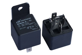
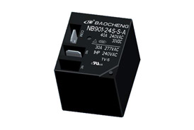
1.Contact forms: they're the arrangements of relay contacts. The basic contact arrangements are shown in table below, the multi-contact arrangments can be ratiocinated.

2.Contact resistance: it is the total resistance between the contacts, the terminals and spring jointed with contacts, generally shown in mΩ.
3.Contact voltage drop: it generally is, in the load circuit, the total voltage drop between contacts,springs jointed with contact and the terminals. It is generally described as the voltage drop value under the regulated current, for example 50mV(measured in 10A).
4.Contact material: it is the material used in contacts and generally shown in chemistry formula, for example, AgNi represents silver-nickel alloy contacts.
5.Contact rated load: it generally refers to the load of which the contacts can switch reliably under the certain regulated conditions. Generally it is shown as the combination of the voltage and the current. The loads listed in the catalogue are resistive loads, unless otherwise stated.
6.Max. switching voltage: it is the maximum load voltage of which relay contacts can switch. In general application, this voltage value shall not be surpassed, or the relay endurance will be reduced.
7.Max. switching current: it is the maximum load current of which relay contacts can switch. In general application, this current value shall not be surpassed, or the relay endurance will be reduced.
8.Max. switch power: it is the maximum load power of which relay contacts can switch reliably. Generally for AC it is shown in VA while for DC it is shown in W.
9.Mechanical endurance: it refers to the operations that relays without load or with load do not lead to failure under the rated voltage, normally switch in the specified, generally it is shown in operations.
10.Electrical endurance: it generally refers to the operations that the relay can normally switch when the specified load is applied on the contacts and the rated voltage is applied to the coil under the conditions that the relay is placed in the certain speculated environment. Generally it is shown in operations.
11.Surge current: it generally refers to the maximum transient current of which relay can endure in the specified load.
12.Min. applicable load: it generally is reference value of minimum load that the relay can switch. Please perform the confirmation test with actual load before production since reference value may change according to switching frequency, environmental condition and expected contact resistance and reliability.


